


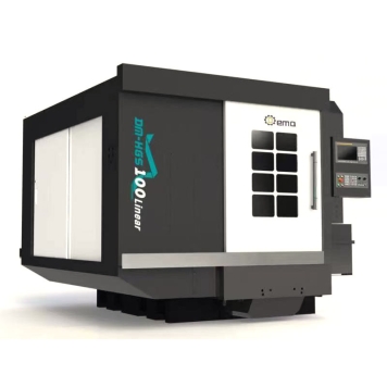
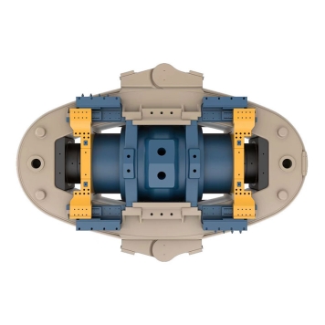
Dema four station spinning machine
1、 Main parameters of the equipment
Project | Unit | Parameter range | |
Processing capability | Machinable wheel hub diameter range | Inches | 14-20 |
Maximum machinable wheel hub width | Inches | 14 | |
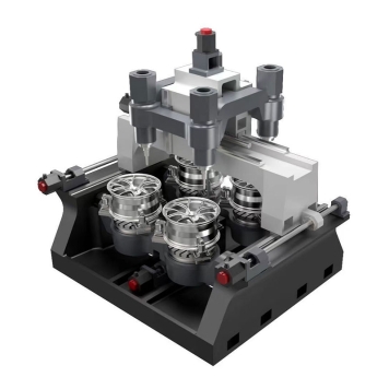
The number of wheel hubs that can be processed simultaneously | Individual | 4 | |
Principal axis | Rated power | kW | 173 |
Maximum spindle torque (individual) | Nm | 3590*3=10770 | |
Lower spindle speed | r/min | 50-500 | |
Spinning wheel | Number of spinning wheels | 个 | 4 |
Wheel diameter | mm | 460-620 | |
Maximum throat depth of the spinning wheel | mm | ≥50 | |
Rotary wheel installation interface | Way | DIN55027-6# | |
Single rotary wheel axial stroke | mm | 500 | |
Maximum axial thrust of a single spinning wheel | kN | 380*2 | |
Maximum axial movement speed | mm/min | 6000 | |
Single rotary wheel radial stroke | mm | 110 | |
Maximum radial thrust of a single spinning wheel | kN | 380*2 | |
Maximum radial movement speed | mm/min | 6000 | |
Caudal crest | Tail top travel | mm | 500 |
Maximum pressure of the tail top cylinder | kN | 350 | |
Discharger | Unloading cylinder thrust | kN | 200 |
Maximum stroke of the unloader | mm | 150 | |
Mold interface | Upper spindle interface | DIN | DIN 55027 SIZE 15 |
Lower spindle interface | DIN | DIN 55027 SIZE 15 | |
Hydraulic system | Rated working pressure | MPa | 17 |
Design maximum pressure | MPa | 17 | |
Communication | Interface | Standard | Ethercat |
Equipment | Mold installation height | mm | 800 |
2、 Innovation and advantages of Dema equipment
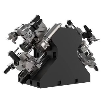
(1) Linkage mechanism feed system
Simple structure, stable performance, and low cost. A set of connecting rods can simultaneously drive two opposite rotary cutting wheels.

(2) Production efficiency increased by 4 times compared to traditional single station spinning machines
A spinning cutter wheel simultaneously processes two products, and a product is processed by two cutters wheels simultaneously (coarse and fine spinning). With the same processing time, the number of completed products increases to four.

(3) Overall finite element simulation
Through finite element analysis, improve the internal stress of each component to ensure that the dimensions of the parts meet safety requirements.

3、 Configuration and performance
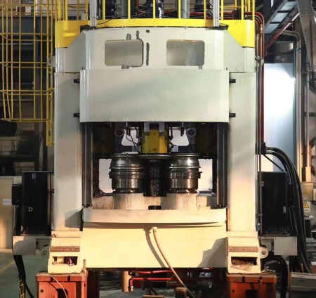
(1) Mechanical structure
The main body of the machine tool uses a combination of high-strength castings, with a compact and reasonable structure, while optimizing the transmission path of rotary pressure. It adopts a closed-loop design, and the force point of rotary processing is closest to the sliding seat.
(2) System electrical appliances
Configure Beifu multi axis CNC system. The electrical system design and installation comply with national standards.
(3) Spindle unit
The spindle is driven by Feishi high torque servo, with a continuously variable speed function. The maximum torque of a single spindle reaches 10770Nm. The spindle box has good vibration absorption and stiffness.
(4) Spinning cutter wheel feed component
The radial feed of the rotary wheel adopts a parallelogram connecting rod structure driven by two hydraulic cylinders on top and bottom to feed synchronously. The connecting rod is made of high-strength alloy steel and ductile iron material.
(5) Main accessories
Number | Name | Standard configuration |
1 | Control system | Feishi |
2 | Belt | Beidi |
3 | Spindle servo motor | Feishi |
4 | Spindle servo driver | Feishi or Beifu |
5 | Oil cylinder seal | Sweden SKF/Austria UTEC |
6 | Bearing | NSk Japan/Scheffler Germany |
7 | Nut | Taiwan YINGSH or equivalent brand |
8 | Electrical components | Schneider |

- Brand
- About Landwheels
- Product Advantages
- Development History
- Certificate of Honor
- Plant and Equipment
- Products
- Land Wheels
- Derma
- Industrial investment
- Land Wheels
- Derma
- QRcode

Technical support:和众互联 浙ICP备********号-2